01. The Introduction of Material
Overview
Until now, the only way to render was to specify images and parameters and do a simple drawing. However, this did not allow complicated rendering such as distorting the image itself or adding specific areas.
Effekseer has materials to accomplish these complex rendering. You can use materials to specify how particles are drawn. Materials can be created in the Material Editor.
Here, let's create a material to create a complex rendering.
The effect created in this chapter
Effects created in this chapter
Basic
Some files have already been prepared. Please download from the link below.
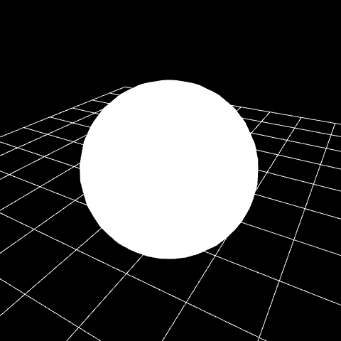
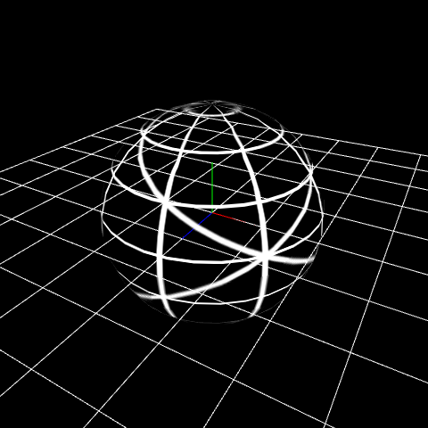
When you open it, you can see that a simple sphere model has been drawn.
In order to create a material, change Material to File in Basic Render Settings.
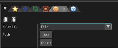
Press the Create button. A dialog for creating a new material appears. When saving material is completed, the material editor starts.
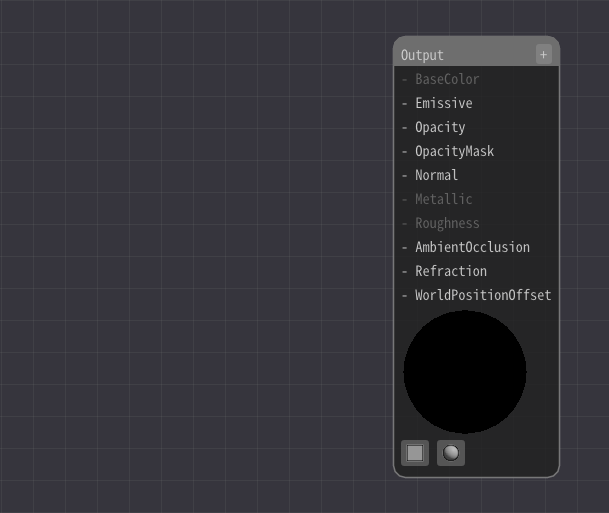
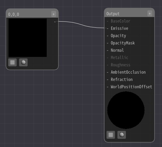
Initially, only Output node exists.
The value connected to this Output node is drawn on the particle.
In the Material Editor, connect these nodes and specify the formula for drawing. The result of the calculation is drawn as particles. It may seem difficult at first, but let's edit it little by little.
The simplest configuration is to connect Constant3 node to the Output node.
Press right click to add a Constant3 node.
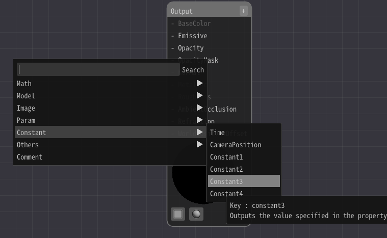
Connect the Constant3 node and Emissive in the Output node.
Then, left-click on the Constant3 node and enter a value from the input field on the left of the screen.
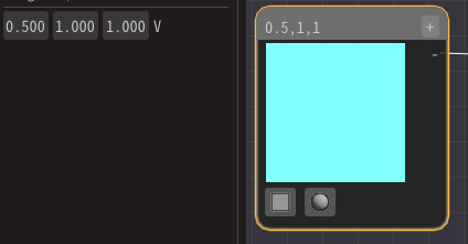
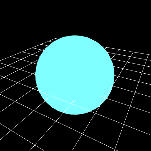
Then, you can see that the color of the sphere changes according to the numerical value.
When adding Constant3 node, did you see that Constant1-4 node existed?
There are several types of values that are transfered between nodes.
It is often a value type consisting of 1 to 4 numerical values, from Number 1 to Number 4. It can also be an image.
Draw an image
Images can be drawn using a Sample Image node.
Right-click to add a Sample Image node.
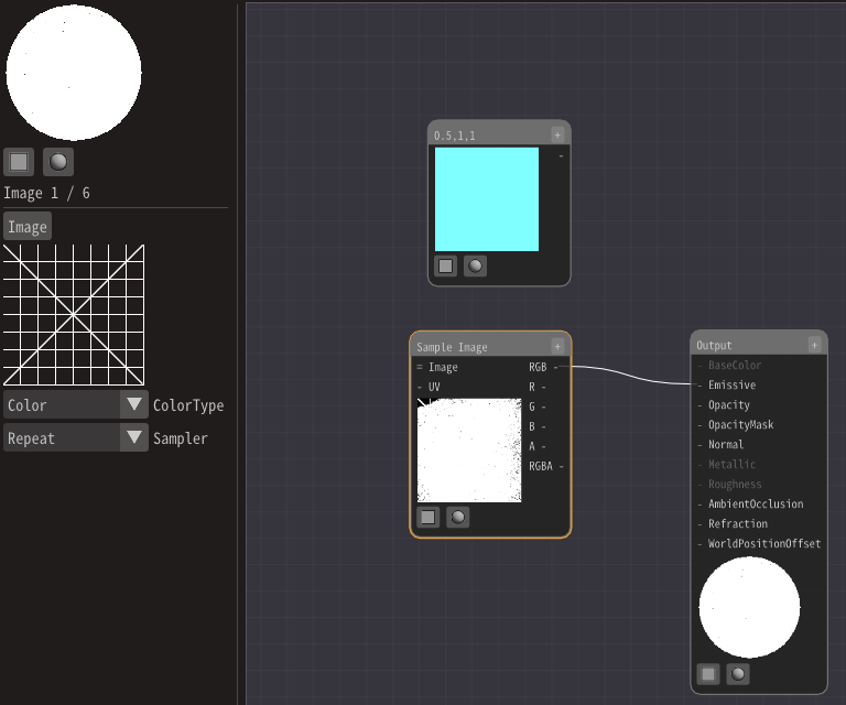
Specify the image from the input field on the left of the screen.
This time, specify Textures/Grid01.png prepared.
Connect RGB in the Sample Image node instead of the Constant3 node.
The image is drawn, but the transparent parts are not transparent.
Therefore, connect A in the Sample Image to Opacity in the Output node.
This connects the transparency of the image to the transparency of the material.
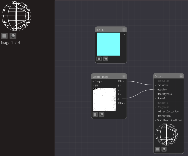
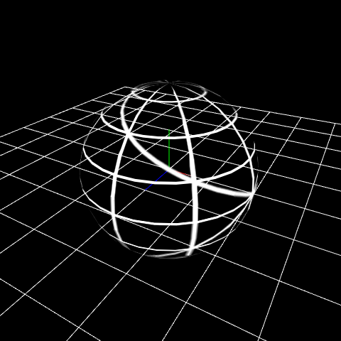
Then, the image was drawn.
Shift an area of drawing image
Until now, the behavior was the same as simply drawing an image on the model. However, various expressions can be made using materials. As a preparation, change the position of the UV coordinates.
UV in the Sample Image is a value indicating the pixel position of the image used for draw.
Let's replace this UV.
Add a UV node.
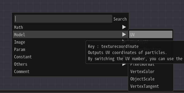
Then, connect to the UV in the Sample Image node.
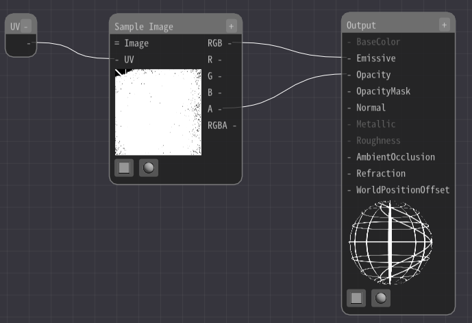
Nothing changes. The reason is that a UV node outputs the UV value of the model or particle as it is.
Let's change this UV value and move the display area of the image.
Add an Add node and a Constant2 node.
Then, connect the Constant2 node and the UV node to the Add node.
Both can be connected because the value type is Number 2.
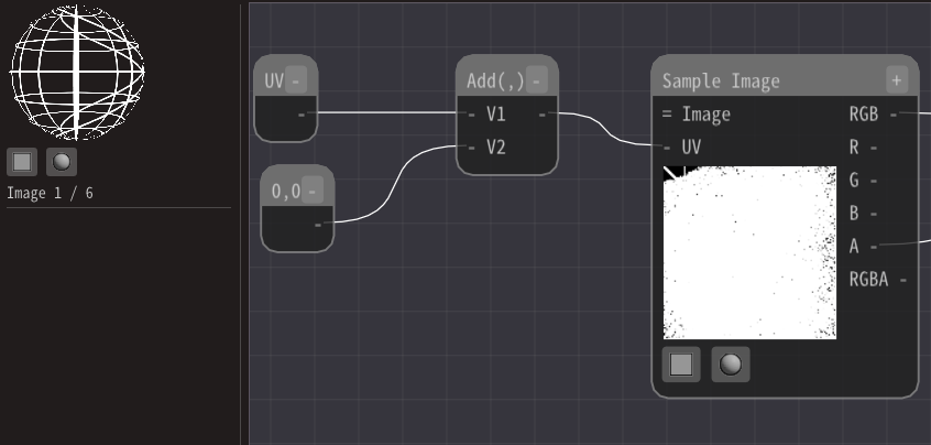
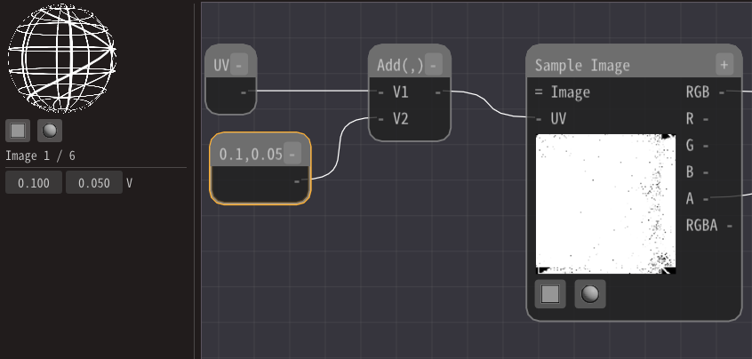
Then, change the value of the Constant2 node. Then you can see that the display position is shifted.
Distort the image
We just shifted the display area of the image, but now let's distort the image.
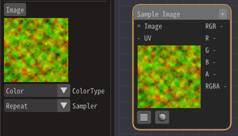
Use an image instead of the Constant2 node.
For the image, specify Textures/Distortion01.png prepared in advance.
Add a Sample Image node and specify the image.
Since the value type of the image is Number 3, use a MaskElements node.
A MaskElements node extracts a part of an element.
Here, we will use the first two values, so check R and G.

Then, connect the MaskElements node to the Add node.
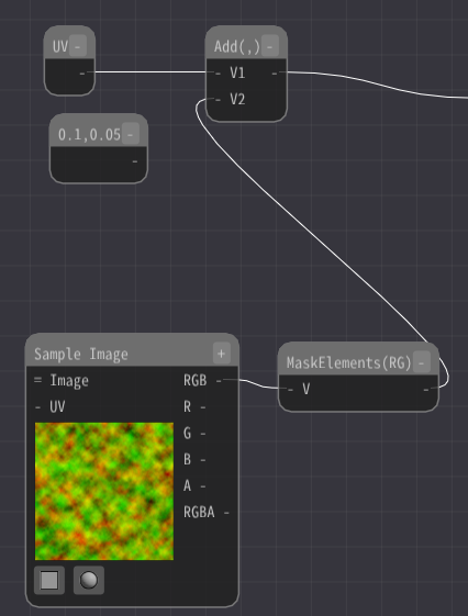
Heavy distortion. But I don't want that distortion.

Use a Multiply node to make it smaller.
Add a Multiply node.
Then, connect the MaskElements node to the Multiply node.
Decrease the value of the Multiply node.
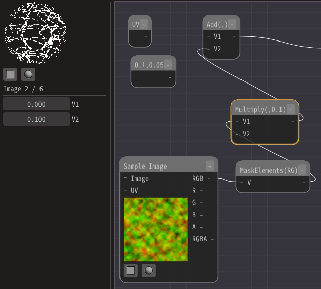
Then it will be distorted well.
Move the distortion
Let's move the distortion because it is quiet when stopped.
Add a MovingUV node.
A MovingUV node outputs the value of the moving UV over time.
Connect this to the Sample Image node.
Change some parameters as well.
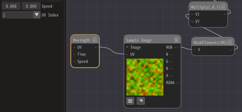
You can see that the distortion moves.
Color
Finally, let's color.
Add a Multiply node.
Connect the Sample Image node that outputs the image and the first fixed 3 nodes added to the Multiply node.
And connect it to Emissive.
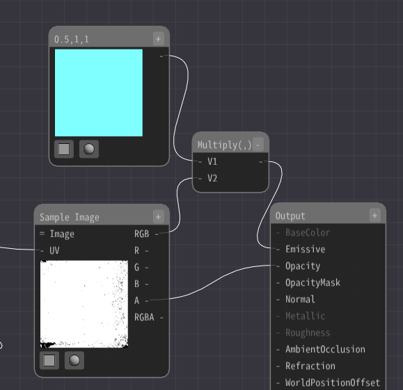
Because the colors are multiplied together, they are colored.
Finally, I made it possible to download the effect created in this chapter.
Samples
This time, we have introduced examples of materials, but we can do various things. Effeksseer has many sample materials, so you may want to look at them.
Summary
This chapter has explained the basics of materials. The use of materials greatly expands the range of expression.